
Communication between Utimaco Atalla HSMs and the Appliances is mediated by the Atalla HSM Connector. It distributes key requests from Key Servers to the HSMs in the cluster to ensure that the load is balanced among the HSMs. The Atalla HSM Connector also detects failed HSMs and redirects requests to the remaining active HSMs. Each Appliance includes the Atalla HSM Connector software, which is disabled by default.
To enable the Atalla HSM Connector service on the Appliance:
-
Complete all installation and configuration steps described in Chapter 1 and Chapter 2 of the OpenText™ Data Privacy and Protection Installation Guide.
-
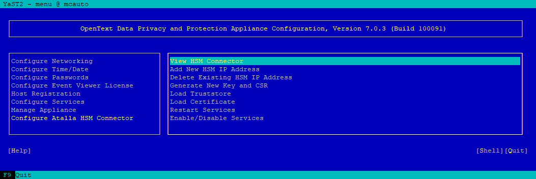
In the Appliance Menu, on the Appliance running the Management Console, navigate to Configure Atalla HSM Connector.
-
Use Down Arrow key to highlight Add New HSM IP Address and then press Enter.
-
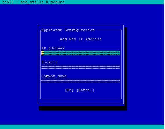
Type the IP address of the Atalla HSM.
-
Tab to the Sockets field, and enter the number of connections needed to the Atalla HSM at that address.
Integers from 2 and 64 are valid. Do not configured more sockets than the value of MAX_ CLIENTS_ASCII in the config.prm file of the HSM. See Update the Configuration File.
If you are connecting to HSMs running firmware version 8.30 or earlier, set two sockets for each Key Server.
If you are connecting to HSMs running firmware version 8.36 or later, refer to the table below to set the number of sockets.
|
Number of Key Server(s) |
1 |
2 |
3 |
4 |
5 |
|
If MC gets key requests |
16 |
10 |
6 |
5 |
4 |
|
If MC does not get key requests |
N/A |
MC: 2 Others: 16 |
MC: 2 Others: 9 |
MC: 2 Others: 6 |
MC: 2 Others: 5 |
To ensure the HSMs can act as clones of one another, all Atalla HSMs used by the Appliance must be of the same type, running the same Atalla software version, and contain the same Master File Key (MFK).
-
Tab to the Common Name field and enter the value (without any leading or trailing white spaces) obtained as the CN= value in the Atalla HSM server certificate, in Step 3 in the section Configure SSL, then choose OK.
-
On the dialog asking if you want to add another IP address, do one of the following:
-
If you are configuring the Appliance to work with multiple Atalla HSMs, choose Yes, and then repeat Step 4 to Step 6 to enter the IP address, number of sockets, and common name (CN) for each Atalla HSM.
-
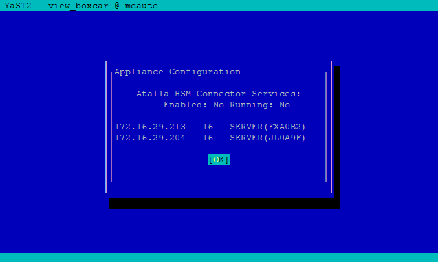
If you have entered all of the required IP addresses, choose No to return to the Atalla HSM Connector IP Address Configuration Menu, which displays the list of all IP addresses and the associated CN value and number of sockets specified for each one.
-
If you are replacing or upgrading an Ax160 to AT1000, perform the following steps to make sure the new Atalla HSM contains the same MFK to support the existing districts:
-
Backup the MFK from the existing Ax160.
-
Disable the HSM checkbox from the Management Console.
-
Restart the vsmgmt service and deploy.
-
Add the new Atalla IP address.
-
Restore the MFK you backed up in step a to the new Atalla HSM.
-
Enable the HSM checkbox from the Management Console.
-
Restart the vsmgmt service and deploy.
-
-
Choose Back to return to the Atalla HSM Connector Configuration Menu. A message displays with a reminder to restart the Atalla Connector Services. However, you do not need to restart the services until after you have configured SSL settings.
-
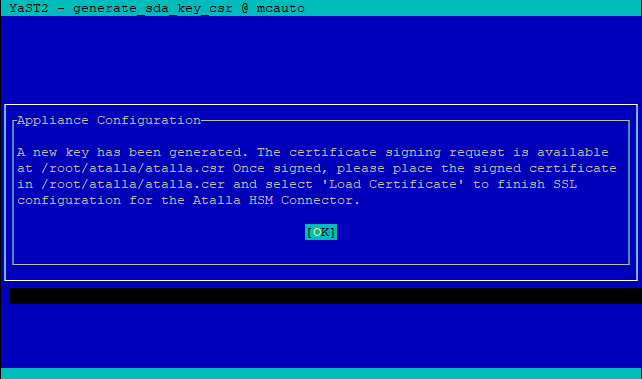
Navigate to Generate New Key and CSR.
-
Enter the Distinguished Name (DN) for the certificate request. The DN field is pre-populated with the value /CN=<host_name>, where <host_name> is the Hostname value that you used in the Configure DNS and Hostname dialog when you initially configured the Appliance.
-
Choose OK, then choose OK again to dismiss the message that shows the location of the
atalla.csrfile.
-
Download the
atalla.csrfile from the/root/atalladirectory of the Appliance. -
Get the CSR signed by your CA and obtain a copy of the root CA certificate.
Make sure to sign the CSR with Client or Client/Server Purpose.
-
Upload the root CA certificate file to the following location on the Appliance:
/root/atalla/truststore.pem
This step assumes that you use the same CA to sign the server certificate and the certificate generated by the Appliance.
If you have a CA chain, you can include the CA chain in the truststore.pem in the following order:
-
CA that signs the client certificate
-
Intermediate certificates
-
Root CA
-
Upload the signed certificate file to the following location on the Appliance:
/root/atalla/atalla.cer -
Choose Load Truststore.
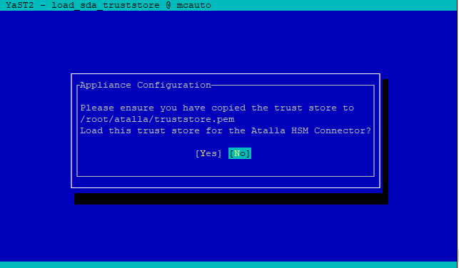
-
Choose Yes to confirm that the
truststore.pemfile is in the correct location and ready to be loaded, then choose No to dismiss the confirmation dialog. -
Choose Load Certificate.
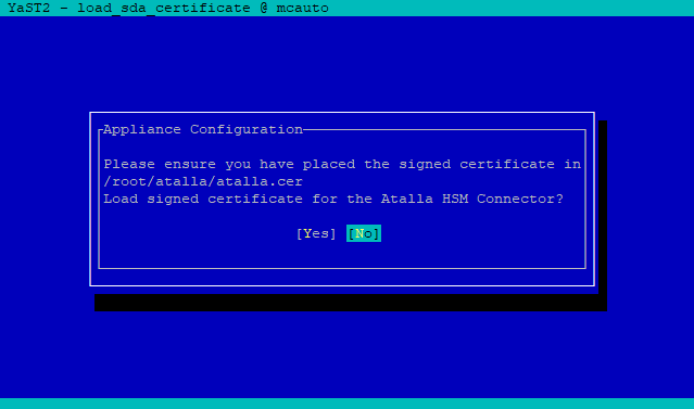
-
Choose Yes to confirm that the certificate is in the correct location and you are ready to load it for use with the Atalla HSM, then choose OK to dismiss the confirmation dialog.
-
Choose Back to return to the Atalla HSM Connector Configuration Menu,
-
Choose Enable/Disable Services and then choose Yes to confirm that you want to enable Atalla HSM Connector services.
-
If you have not already done so, verify that the time on the Appliance is correct, and if needed, set the date/time manually or from the NTP server.
-
Complete Step 1 to Step 22 for each Appliance that serves as a remote host running a Key Server.